
Condenser, Compressor & Lines for 2025 Chevrolet Express 3500
Categories
- Aero Ground Effects & Body Kits
- Back Door
- Brackets, Flanges & Hangers
- Bumper
- Bumper & Components - Front
- Bushings
- Center Pillar
- Cluster & Switches
- Console
- Control Cables
- Cowl
- Dashboard
- Door & Components
- Doors
- Driver Seat Components
- Ducts
- Electrical Components
- Exterior Trim - Back Door
- Exterior Trim - Pillars
- Exterior Trim - Rear Body
- Exterior Trim - Side Panels
- Fender & Components
- Fenders
- Floor
- Frame
- Frame & Components
- Front Console
- Front Door
- Front Door Trim
- Gaskets & Sealing Systems
- Glass - Front Door
- Glass - Side Door
- Glass - Windshield
- Glass & Hardware - Back
- Glass & Hardware - Body Side
- Glass, Windows & Related Components
- Grille
- Grille & Components
- Hardware, Fasteners & Fittings
- Hinge Pillar
- Hood
- Hood & Components
- Horns
- Information Labels
- Inner Components
- Inner Structure
- Instrument Panel
- Interior Trim - Back Door
- Interior Trim - Cowl
- Interior Trim - Front Door
- Interior Trim - Pillars
- Interior Trim - Rear Body
- Interior Trim - Roof
- Interior Trim - Side Door
- Interior Trim - Side Panels
- Labels
- Lid & Components
- Lock & Hardware
- Master Cylinder - Components On Dash Panel
- Mirrors
- Outside Mirrors
- Passenger Seat Components
- Quarter Panel
- Radiator Support
- Rear Body
- Rear Bumper
- Rear Floor & Rails
- Rear Seat Components
- Reveal Moldings
- Rocker Panel
- Roof
- Roof & Components
- Seat Belt
- Seats
- Sensors
- Side Door
- Side Panel & Components
- Side Pillar
- Sliding Door
- Sound System
- Spare Tire Carrier
- Steering Wheel
- Switches, Solenoids & Actuators
- Trailer Hitch Components
- Trunk Lid & Compartment
- Uniside
- Wiper & Washer Components
- Wire, Cable & Related Components
- ABS Components
- Anti-Lock Brakes
- Brackets, Flanges & Hangers
- Brake Components
- Brake Hydraulics
- Control Modules
- Disc Pads & Brake Shoes
- Drums & Rotors
- Front Brakes
- Gaskets & Sealing Systems
- Hardware, Fasteners & Fittings
- Hoses & Pipes
- Hydraulic Booster
- Hydraulic System
- Parking Brake
- Rear Brakes
- Sensors
- Service Kits
- Switches, Solenoids & Actuators
- Traction Control
- ABS Components
- Air Bag Components
- Air Bag System
- Alternator
- Alternator/Generator & Related Components
- Antenna & Radio
- Anti-Theft Components
- Anti-Theft System
- Automatic Transmission
- Back Door
- Battery
- Battery & Related Components
- Bulbs - Chassis
- Communication System Components
- Control Modules
- Controls
- Electrical Components
- Electrical Connectors
- Electrical Sockets
- Flasher Units, Fuses, & Circuit Breakers
- Front Door
- Front Seat Belts
- Fuse & Relay
- Glass, Windows & Related Components
- Hardware, Fasteners & Fittings
- Headlamp Components
- High Mounted Stop Lamp
- Horn
- Ignition Lock
- Ignition System
- Instruments & Gauges
- Keyless Entry Components
- Lane Departure Warning
- License Lamps
- Lighting - Exterior
- Lighting - Instrumentation
- Lighting - Interior
- Mirrors
- Mobile Multi-Media
- Navigation System
- Park & Signal Lamps
- Parking Aid
- Power Outlets
- Power Seats
- Powertrain Control
- Rear Seat Belts
- Seat Belt
- Senders
- Sensors
- Side Door
- Sliding Door
- Starter
- Starter & Related Components
- Steering Column
- Steering Wheel
- Switches
- Switches, Solenoids & Actuators
- Tail Lamps
- Tire Pressure Monitor Components
- Wipers
- Adapter Housing
- Air Intake
- Bearings
- Brackets, Flanges & Hangers
- Control Modules
- Cylinder Block Components
- Engine
- Engine & Trans Mounting
- Engine Parts
- Filters
- Gaskets & Sealing Systems
- Hardware, Fasteners & Fittings
- Mounts
- Oil Cooler
- Oil Pan
- Oil Pump
- Pumps
- Sensors
- Switches, Solenoids & Actuators
- Valve Train Components
- A/C Accumulator/Receiver Drier
- A/C Clutch & Compressor
- A/C Condenser & Evaporator
- A/C Flow Restrictors
- Air Heater Components
- Automatic Temperature Controls
- Auxiliary Heater & AC
- Blower Motor & Fan
- Brackets, Flanges & Hangers
- Condenser, Compressor & Lines
- Control Modules
- Controls
- Evaporator & Heater Components
- Evaporator Components
- Gaskets & Sealing Systems
- Hardware, Fasteners & Fittings
- Heater
- Heater Components
- Hoses & Pipes
- HVAC Case
- Motors, Core, Case & Related Components
- Relays
- Sensors
- Switches & Sensors
- Switches, Solenoids & Actuators
- Temperature Controls & Related Components
- Wire, Cable & Related Components
- Bearings
- Brackets, Flanges & Hangers
- Gaskets & Sealing Systems
- Hardware, Fasteners & Fittings
- Lower Components
- P/S Pump & Hoses
- Power Steering Hoses, Pumps, & Related Components
- Pump & Hoses
- Sensors
- Shaft & Internal Components
- Shroud, Switches & Levers
- Steering Column
- Steering Column Assembly
- Steering Gear & Linkage
- Steering Wheel
- Steering Wheel & Trim
- Steering, Gear & Related Components
- Wire, Cable & Related Components
Browse Categories
Select category
- Aero Ground Effects & Body Kits
- Back Door
- Brackets, Flanges & Hangers
- Bumper
- Bumper & Components - Front
- Bushings
- Center Pillar
- Cluster & Switches
- Console
- Control Cables
- Cowl
- Dashboard
- Door & Components
- Doors
- Driver Seat Components
- Ducts
- Electrical Components
- Exterior Trim - Back Door
- Exterior Trim - Pillars
- Exterior Trim - Rear Body
- Exterior Trim - Side Panels
- Fender & Components
- Fenders
- Floor
- Frame
- Frame & Components
- Front Console
- Front Door
- Front Door Trim
- Gaskets & Sealing Systems
- Glass - Front Door
- Glass - Side Door
- Glass - Windshield
- Glass & Hardware - Back
- Glass & Hardware - Body Side
- Glass, Windows & Related Components
- Grille
- Grille & Components
- Hardware, Fasteners & Fittings
- Hinge Pillar
- Hood
- Hood & Components
- Horns
- Information Labels
- Inner Components
- Inner Structure
- Instrument Panel
- Interior Trim - Back Door
- Interior Trim - Cowl
- Interior Trim - Front Door
- Interior Trim - Pillars
- Interior Trim - Rear Body
- Interior Trim - Roof
- Interior Trim - Side Door
- Interior Trim - Side Panels
- Labels
- Lid & Components
- Lock & Hardware
- Master Cylinder - Components On Dash Panel
- Mirrors
- Outside Mirrors
- Passenger Seat Components
- Quarter Panel
- Radiator Support
- Rear Body
- Rear Bumper
- Rear Floor & Rails
- Rear Seat Components
- Reveal Moldings
- Rocker Panel
- Roof
- Roof & Components
- Seat Belt
- Seats
- Sensors
- Side Door
- Side Panel & Components
- Side Pillar
- Sliding Door
- Sound System
- Spare Tire Carrier
- Steering Wheel
- Switches, Solenoids & Actuators
- Trailer Hitch Components
- Trunk Lid & Compartment
- Uniside
- Wiper & Washer Components
- Wire, Cable & Related Components
- ABS Components
- Anti-Lock Brakes
- Brackets, Flanges & Hangers
- Brake Components
- Brake Hydraulics
- Control Modules
- Disc Pads & Brake Shoes
- Drums & Rotors
- Front Brakes
- Gaskets & Sealing Systems
- Hardware, Fasteners & Fittings
- Hoses & Pipes
- Hydraulic Booster
- Hydraulic System
- Parking Brake
- Rear Brakes
- Sensors
- Service Kits
- Switches, Solenoids & Actuators
- Traction Control
- ABS Components
- Air Bag Components
- Air Bag System
- Alternator
- Alternator/Generator & Related Components
- Antenna & Radio
- Anti-Theft Components
- Anti-Theft System
- Automatic Transmission
- Back Door
- Battery
- Battery & Related Components
- Bulbs - Chassis
- Communication System Components
- Control Modules
- Controls
- Electrical Components
- Electrical Connectors
- Electrical Sockets
- Flasher Units, Fuses, & Circuit Breakers
- Front Door
- Front Seat Belts
- Fuse & Relay
- Glass, Windows & Related Components
- Hardware, Fasteners & Fittings
- Headlamp Components
- High Mounted Stop Lamp
- Horn
- Ignition Lock
- Ignition System
- Instruments & Gauges
- Keyless Entry Components
- Lane Departure Warning
- License Lamps
- Lighting - Exterior
- Lighting - Instrumentation
- Lighting - Interior
- Mirrors
- Mobile Multi-Media
- Navigation System
- Park & Signal Lamps
- Parking Aid
- Power Outlets
- Power Seats
- Powertrain Control
- Rear Seat Belts
- Seat Belt
- Senders
- Sensors
- Side Door
- Sliding Door
- Starter
- Starter & Related Components
- Steering Column
- Steering Wheel
- Switches
- Switches, Solenoids & Actuators
- Tail Lamps
- Tire Pressure Monitor Components
- Wipers
- Adapter Housing
- Air Intake
- Bearings
- Brackets, Flanges & Hangers
- Control Modules
- Cylinder Block Components
- Engine
- Engine & Trans Mounting
- Engine Parts
- Filters
- Gaskets & Sealing Systems
- Hardware, Fasteners & Fittings
- Mounts
- Oil Cooler
- Oil Pan
- Oil Pump
- Pumps
- Sensors
- Switches, Solenoids & Actuators
- Valve Train Components
- A/C Accumulator/Receiver Drier
- A/C Clutch & Compressor
- A/C Condenser & Evaporator
- A/C Flow Restrictors
- Air Heater Components
- Automatic Temperature Controls
- Auxiliary Heater & AC
- Blower Motor & Fan
- Brackets, Flanges & Hangers
- Condenser, Compressor & Lines
- Control Modules
- Controls
- Evaporator & Heater Components
- Evaporator Components
- Gaskets & Sealing Systems
- Hardware, Fasteners & Fittings
- Heater
- Heater Components
- Hoses & Pipes
- HVAC Case
- Motors, Core, Case & Related Components
- Relays
- Sensors
- Switches & Sensors
- Switches, Solenoids & Actuators
- Temperature Controls & Related Components
- Wire, Cable & Related Components
- Bearings
- Brackets, Flanges & Hangers
- Gaskets & Sealing Systems
- Hardware, Fasteners & Fittings
- Lower Components
- P/S Pump & Hoses
- Power Steering Hoses, Pumps, & Related Components
- Pump & Hoses
- Sensors
- Shaft & Internal Components
- Shroud, Switches & Levers
- Steering Column
- Steering Column Assembly
- Steering Gear & Linkage
- Steering Wheel
- Steering Wheel & Trim
- Steering, Gear & Related Components
- Wire, Cable & Related Components
Condenser, Compressor & Lines for 2025 Chevrolet Express 3500
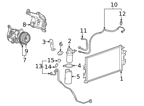 1. ACDelcoâ„¢ Condenser
 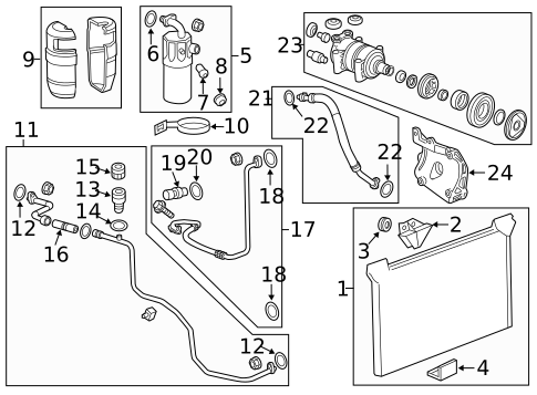 2. Accumulator Cap
  3. A/C Line O-Ring
  4. A/C Line O-Ring
  5. ACDelcoâ„¢ A/C Service Valve Core
  6. ACDelcoâ„¢ A/C Service Valve Cap
  7. Rear Press Tube Cap
 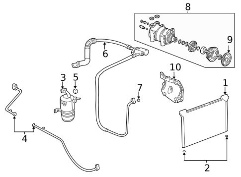 8. AC Line O-Ring
 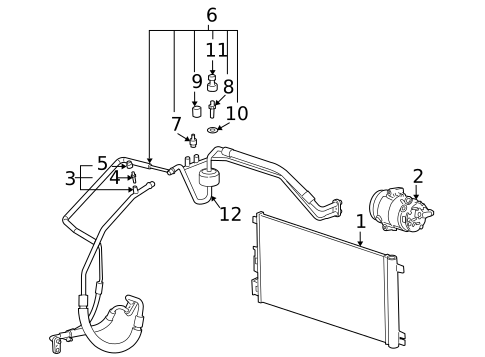 9. Hose & Tube Assembly Cap
 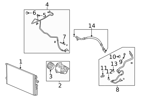 10. Return Line Assembly Cap
 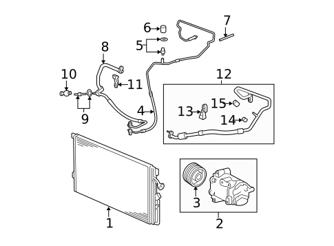 11. Upper
 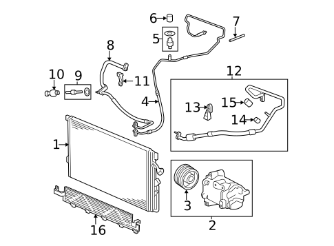 12. Return Line Cap
 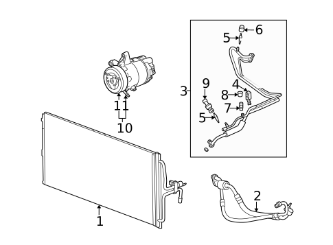 13. Core Cap
 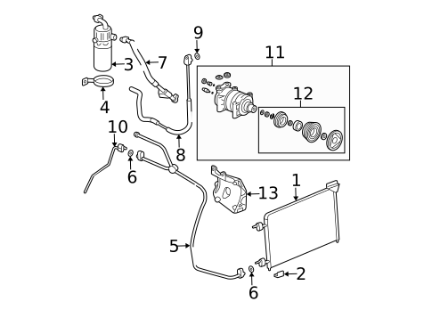 14. AC Line O-Ring
 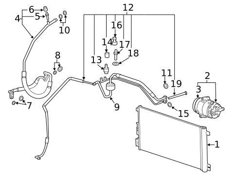 15. Hose & Tube Assembly Cap
 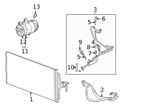 16. Core Cap
 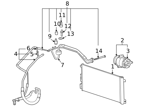 17. Hose & Tube Assembly Cap
 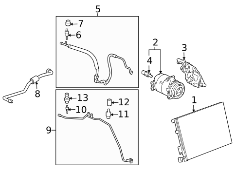 18. Pressure Hose Cap
 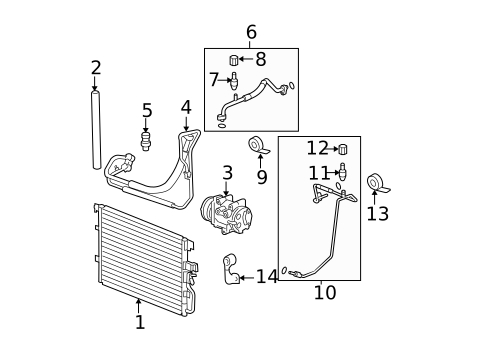 19. Evaporator Tube Cap
 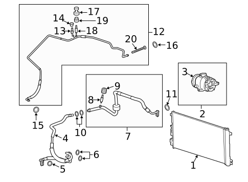 20. Rear Suction Hose Cap
  21. Service Valve Cap
  22. Cap
 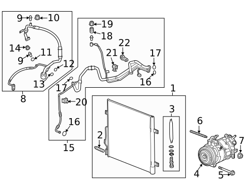 23. Pressure Hose Cap
 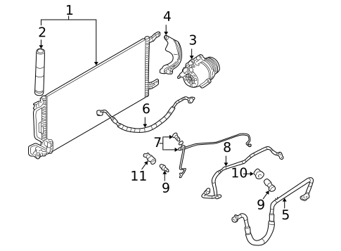 24. Bleeder Valve Cap
  25. A/C Service Valve Cap
  26. Hose & Tube Assembly Cap
 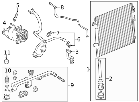 27. Hose & Tube Assembly Cap
 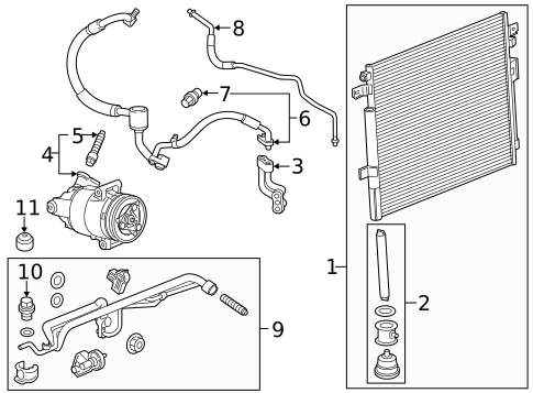 28. Hose & Tube Assembly Cap
  29. Cap
 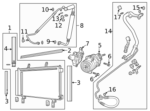 30. Pressure Hose Cap
 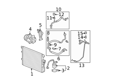 31. Evaporator Tube Cap
 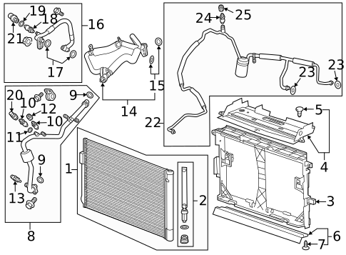 32. Front Suction Hose Cap
  33. Rear AC Tube Cap
 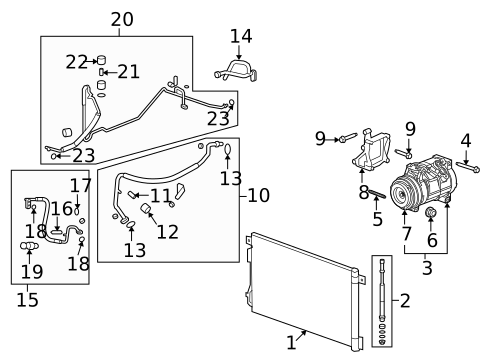 34. Front Suction Hose Cap
 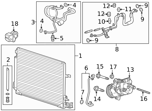 35. Rear AC Tube Cap
 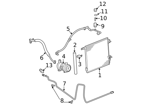 36. Service Valve Cap
 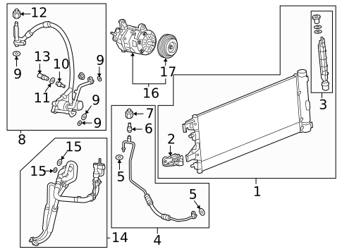 37. A/C Service Valve Cap
 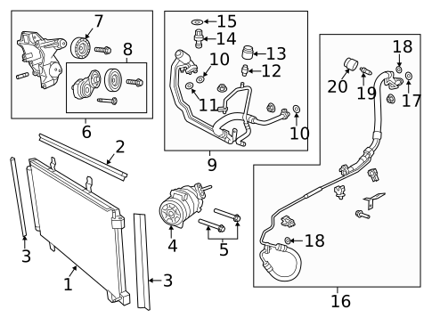 38. Pressure Hose Cap
  39. Hose & Tube Assembly Cap
  40. Pressure Hose Cap
 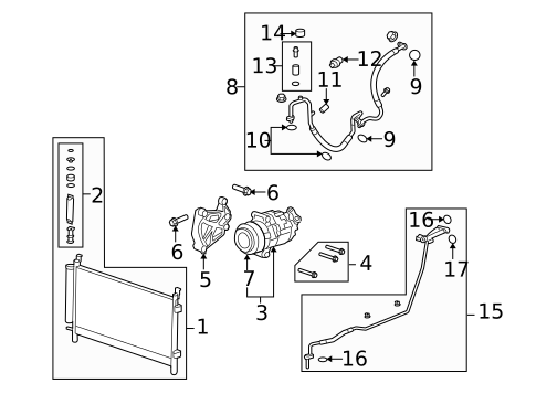 41. Service Valve Cap
  42. Suction Hose Cap
  43. Evaporator Tube Cap
 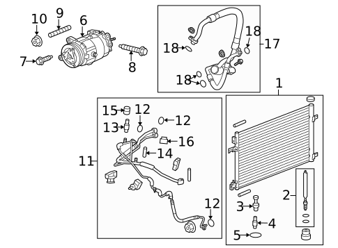 44. ACDelcoâ„¢ A/C Service Valve Cap
 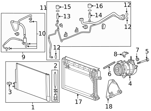 45. Rear
  46. Service Valve Cap
 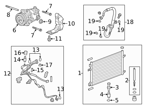 47. Pressure Hose Cap
 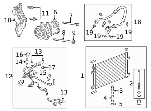 48. ACDelcoâ„¢ A/C Service Valve Cap
  49. Valve Cap
 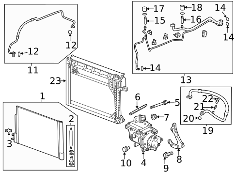 50. Rear
  51. Liquid Line Cap
 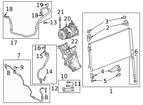 52. A/C Service Valve Cap
 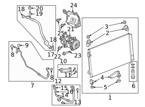 53. Rear
 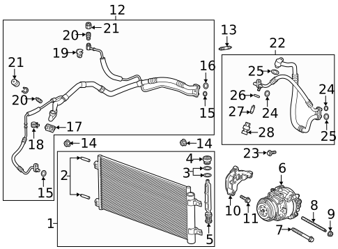 54. Discharge Hose Cap
 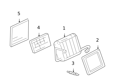 55. Front
  56. AC Line O-Ring
 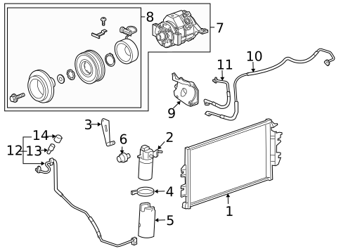 57. Compressor Assembly
  58. Compressor Assembly
  59. Clutch
 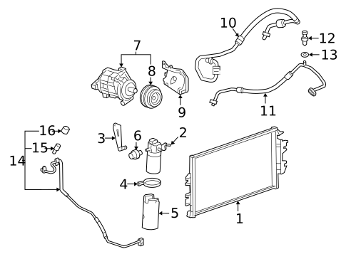 60. Clutch
  61. Service Valve Seal
  62. A/C Refrigerant Line O-Ring
  63. Compressor
 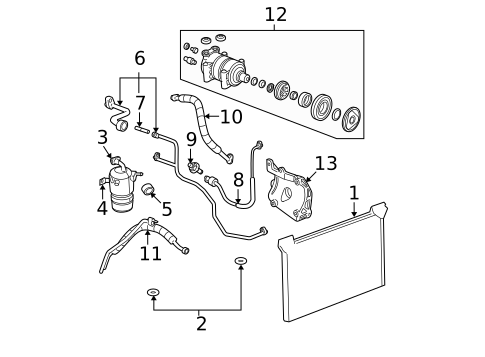 64. Compressor
  65. Evaporator Tube Seal
  66. Service Valve Seal
  67. Service Valve Seal
 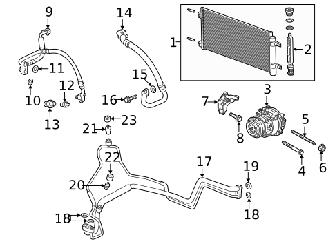 68. A/C Refrigerant Line O-Ring
 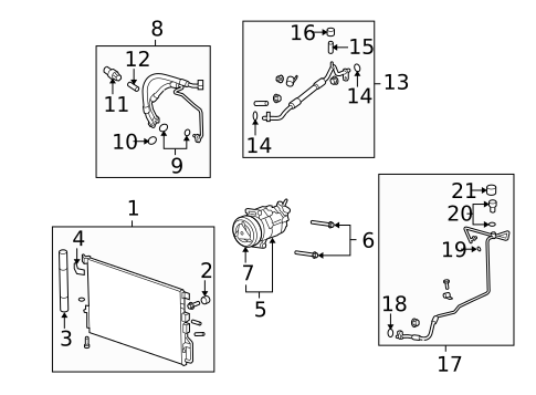 69. Rear Press Hose Cap
 no image
No.
Part # / Description / Price
Price
5

Air Conditioning Service Valve  GM
GM
GM Description: Repairs leaking A/C system
Restores A/C function
This GM Genuine Part is designed, engineered, and tested to rigorous standards and is backed by General Motors
Original equipment parts are designed to work with your GM vehicle safety systems -- aftermarket replacement parts may not meet the same OE safety regulations, depending on the part type
MSRP $25.22
$16.39
MSRP $25.22
$16.39
8

Compressor GM
GM Description: Express 3500. 4.3l. Savana 3500. 4.3l. Express 2500. 4.3l. Savana 2500. 4.3l. Express 2500. 6.6l. Express 3500. 6.6l. Savana 2500. 6.6l. Savana 3500. 6.6l.
MSRP $652.47
$411.06
MSRP $652.47
$411.06